This is the 4th post in a series on building a well house,
and I hope you will look at the previous posts
to get up to speed on this project:

In the last post we finished the block walls and bond beam,
and the 5/8" x 12" anchor bolts (or J bolts) embedded in the bond beam
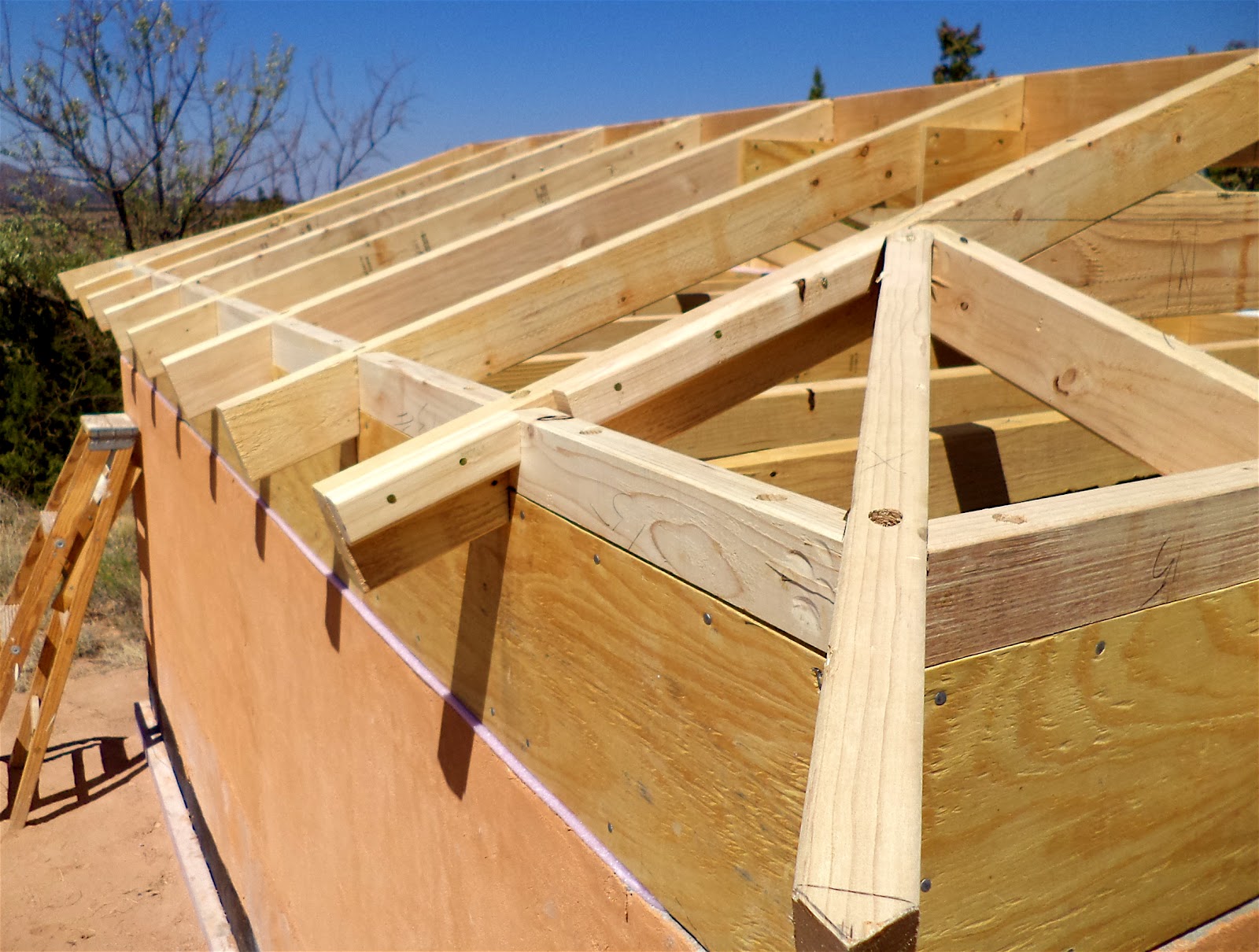
gave us an extra 7 1/2" to raise up the top plate as you can see above.
The well house will have a pretty low ceiling (82")
which will help to keep it warm in the winter using the trombe wall solar collector,
and the extra height at the plate saved us from lifting block
and concrete up to the top of the wall.
The raised plate also gives us extra space to insulate the top of the block wall,
a critical area for heat loss in any masonry structure;
and the juncture of wall and roof in any building, including frame,
is usually the weak link in the insulated envelope.
This little frame wall is the width of the block wall
(allowing for 1/2" plywood sheathing on each side),
has pink foam seal between the concrete bond beam and the the first plate,
and of the 3 wood plates shown above,
the anchor bolts are bolted to the middle plate.
The very top plate is 2x4"s nailed to the middle plate.
For a hip roof (really any roof but especially the hip)
it is critical that the plates be level and square,
otherwise it throws the whole roof off.

The 2"x4" ceiling framing (above) is preassembled and just dropped into place.
Between the ceiling joists will be filled with rigid foam insulation
and on top of the joists will be a continuous layer of 2" XPS,
to cover any thermal breaks created by the joists.
I have always limited my use of rigid foam because of environmental issues
but for this application I felt it would be best
as I was concerned about potential moisture build up in the well house
compromising fiberglass or cellulose insulation.
When it comes to insulation there are rarely any easy answers,
unless maybe you are building with straw bale.

As you can see above the entire void between the plates
is also filled with scraps of rigid foam insulation.

Above you can see the plywood side sheathing is on
and I have enough rafters to hold up the ridge beam.

I think the hip roof is the superior roof style which I have mentioned before in the posts:
as the overhang protects all 4 sides of the building
and sense there are no exposed gable ends wind is deflected better.
The hip roof also creates a lower profile for the whole building.
I have a lot of fun using the roof framing square (strange but true)
to figure the lengths and angle cuts of each rafter before I ever put them up,
especially the diagonal hip rafter as seen above,
but I am really not qualified to explain the process in detail in this blog
other than to recommend getting a used textbook or other book on residential framing.
Many years ago I found a used textbook (Residential Carpentry by John Capotosto)
in an antique store that has served me well
and other than a critical misprint has a pretty clear explanation for framing up the hip roof.
This roof is actually a dutch hip roof
which means there are small gable ends at each end
which are great for providing extra venting for the attic space.
Above you can see the framing is complete
including blocking between the rafters along the top plate,
and as you may notice the overhang is only 6"
so that the roof does not shade the future solar Trombe wall.
Because of it's small size this roof was pretty easy to frame
and there were no jack rafters (the rafters that emanate from the hip rafter)
with their compound angle end cuts.
I usually use eave vents for venting the attic area
but as you can see above I have not included any vents under the eaves
since there will be small vents at the gable ends as well as a continuous ridge vent.
Also above notice the hip rafter at the corner;
the angle of the end cut of the rafter tail
is the only part of the roof that can I cannot figure on the ground.
If I used a plumb cut instead of a square cut on the end I can use the roof framing square
but with a square cut, as I use, it must be marked in place;
hmmm, any advanced carpenters out there?

I like to connect the common rafters with plywood gussets
whose shape is determined by the scraps I have lying around (above).

Above shows the pattern rafter that I use for marking out all the common rafters.
The plumb line drawn on the right is the length of the shorter common rafters on each end
and the horizontal lines over the plate were to compare different bird mouth cuts.

Instead of metal tie downs on the rafters I use solid blocking
that insures these rafters will never blow off.
A technique that makes nailing the rafters and blocking much easier
and more solid is to drill 5/8" holes first to an appropriate depth
so I can nail vertically instead of toe nailing
and use the nail punch you see above to set the 16 penny nails into the top plate.
I believe I got the nail punch at a farm auction many years ago
but any short metal bar stock should work.
Once the vertical nails are set it is easy to add additional toe nails as necessary.
The small void beside the plate is filled with small scraps of pink insulation
and before the sheathing was being put up on the roof
Allison carefully cut around the rafters for rigid insulation to go over the ceiling joists
to create a solid 2" of foam over the ceiling joists
and top plate up to the blocking between the rafters.

We used 1/2" exterior plywood which we felt was plenty
over the 16" on center rafters and on top of that will be 3/4" purlins.
I normally would not use the plywood and instead just have the purlins
but we have a pretty bad deer mouse problem and I wanted to seal them out.
As luck would have it the roof took 3 sheets of plywood with virtually no waste;
the 80"x128" (which works out to 16" centers) footprint
has worked out well in not leaving a lot of scrap material
at the various stages of construction,
something to consider when designing any building.

Along the ridge and at the gable ends are the vents
which I covered with 1/8" hardware cloth to keep out the mice and insects.
In the next post we will look at the metal roof.
Here are links to the whole series up to this point: